I tied up a few loose ends hardware wise, and decided to do some rough testing with the extruder. In order to drive the stepper, I connected it to the 4th axis output of my mill. I turned on the heater circuit, and waited until it hit temp. Then I turned on the stepper power system. This is where the trouble started.
Temperature readings began jumping around wildly, which caused the actual temperature to drop, the system would see that the temp was reading very high and turn the heater off. I was reading the temp through the serial port monitor on the Ardunio. Thinking it might have been a strange ground loop problem, or timing interference on the CNC system with the serial monitor I tried isolating the board. Separate board power supply, and I attached a serial LCD display for temp readout. No difference, still crazy noise when the CNC was on.
I thought noise might be getting through the thermocouple, so I grounded the shield with no change. Although I checked for conduction paths between everything and the thermocouple, I even tried taking the thermocouple off the extruder and moving it and the board across the room.
A little scoping around and I believe I have found the culprit, the switching power supply that drives the CNC. When it's on there is enough noise radiated back into the power line to put 50mv of noise on an oscilloscope with it's probe grounded that is plugged into the same house circuit. An EMI filter is on it's way from Digikey. A new power supply is being researched as well, as I plan on making an all in one power source/cnc controller and I need a supply that will play nice in that app.
The other big thing is that I have decided I am not satisfied with the current extruder design. Although it does function relatively well, I am not happy with it's ease of manufacture. Too many operations on too many parts, and absent a bunch of fixtures, very time consuming to make en masse. Additionally the whole thing seemed rather heavy, and reducing weight in this area would seem crucial to good performance.
I have almost completed a reworking of the heater block, nozzle, tube and heatsink parts. I am still working on a redesign of the filament drive mechanics. This where I feel the most can be gained, this part weighs the most.
Sunday, October 17, 2010
Sunday, October 10, 2010
Electronics 1
Since I am not using the standard electronics to control the stepper motors, I needed to come up with something for temperature control for the extruder head. I could have bought an off the shelf extruder controller and just not used the features on the board that I didn't need. That seemed like a bad solution, and I'd have to add another board anyway to get the thermocouple signal in. I've designed boards before and had them produced by external services, but I didn't want to wait/pay for that this time. I do have a CNC mill at my disposal, and I wanted to try milling a board.

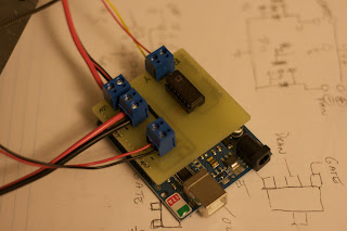


Since the circuit was so simple I designed this in Solidworks rather than a schematic CAD program. The circuit consists of an AD595 to convert the temperature from a type K thermocouple, and a pair of NIF5003 FET's to control power to the heater resistor, and the fan for cooling the heater heat sink. I milled this board using a combination of 1/16" and 1/32" end mills, cutting .003" thick. It's key to make sure that the board is very flat when milling, as errors of a couple of thou will easily be reflected in a cut that shallow. I faced a small metal plate in the vise first, to make sure it was as flat as the mill could make it before double stick taping the board down. I am quite pleased with the result, I'll have to make more boards like this in the future.


Here is the board on top of the Ardunio board I have. You can see the AD595 on top in a socket (no sense committing a $20 chip until you know the circuit works). The two FET's are hidden on the bottom of the board, as they are surface mount, and I only felt like doing a single sided board.
I whipped up some really rough test code to see if I could get some temperature control out of this thing. I'm happy to report that it seems to work well so far. I should really get another thermocouple to confirm temp accuracy. You can also see the PTFE insulator parts around the heater block in the second picture. There are still some minor mechanical things to finish before I can start pumping plastic through it, with any luck I can get that happening later this week.
Saturday, October 9, 2010
The first toolhead nears completion

There was one major part missing from the assembly thus far. There is a need for an easily switchable toolhead so that several designs can be experimented with. I have some rough designs in my head for a much finer extrusion, and hopefully reducing the mass of the extruder significantly. A switchable design will also let me drop in a tangential knife setup, or other options, more on those in a minute. The other big thing that I've not seen is a safety system to protect the head in the event of a crash, and notify the system. Such a system is essential to protect the system during an unattended print if something goes wrong. The lasers at work have a similar system that if the actual head contacts the work, it simply alarms out, and the nozzle is easily pushed back to precise alignment.
Good news is that I think I can kill several birds with one stone. I've basically adopted the same methodology as some simpler 3D probe systems. The above pictured item is kind of the keystone in this setup. Three dowel pins are mounted at 120 degrees to each other. These will set on pairs of bearing balls, providing two points of contact per dowel pin. With 3 pins there will be repeatable location every time. By electrically connecting the balls in series, you can sense if the unit is located or not. By applying spring pressure to the top the extruder will stay still, but if the tip gets knocked away by a warped or attached part the system can safely stop. By mounting a stylus head instead of the extruder you could scan simple objects into point clouds. If nothing else you can determine the exact level of the bed of the machine using this method.

Now I can put together the extruder head. Except for the #8 bolts I'm missing....doh! At least things have gone together enough for this shot. Todays work involves drawing and hopefully cutting the PTFE insulators for the heater block. I'll get the bolts tomorrow. I'd really like to melt some plastic by the end of the weekend, but there's a long way to go.
After much internal debate I have also decided to go with non RepRap electronics. I have a viable CNC drive system already done. The Gecko 4 axis drive that I have uses 9 pin DIN connectors to plug steppers into. Within these connectors there is a current set resistor installed for each motor, so the drive is set per the motor that is plugged in. This will make it easy to make a CNC drive box with the stepper power supply, the 4 axis drive, and the USB step pulse generator. Connections available for limit switches and such available, I'll develop a multi-pin solution so all I need to do is connect 4 steppers and one other plug to switch machines.
Tuesday, October 5, 2010
Filament Drive

Today I worked on the housing for the filament drive system. Pretty simple really, a couple of 1/8" thick aluminum plates, and some delrin to space them apart. As previously mentioned, the drive roller and larger pulley spin on needle roller bearings against a 1/4" diameter shoulder bolt. The front side of the housing has an adjustable shaft that the idler roller rides on. The idler roller is a bronze bushing with rubber bonded to it.

In this side view you can kind of see how all of the pieces fit together. Although I haven't put power to the stepper yet it seems to have plenty of grip on the PLA that I have. It's really hard to see in these pictures, but the delrin is cut for some pieces of 3/8" PTFE rod that I had from another project. I'll drill them out to provide top and bottom guide tubes for the filament. The bottom tube will extend all the way down into the heatsink.
Friday, October 1, 2010
Test Assembly


Progress is a bit slower than I'd like, but I did manage to get enough things done to put together this test assembly of the hot end. I have a 3A 12V power supply kicking around, so I wired it up. I also connected the thermocouple which was removed to take these shots.
The heater reached 210C pretty quickly, I'd say about a minute and a half, possibly less. I didn't leave it connected, as I don't have the circuit boards for the extruder controller put together yet, just connect/disconnect while watching the meter. In this limited test the heatsink stayed relatively cool. More testing is needed to see how it holds up under actual use.
Wednesday, September 29, 2010
Filament Drive

I use a .25" shoulder bolt for an axle. They come reasonably precise, and with a hardened, ground shoulder perfect for running the needle roller bearings on. The drive roller itself is a piece of 360 brass .625" in diameter. The center was drilled and reamed to the bearings OD, .4375", for a nice press fit. I then bored the pulley out to fit this assembly. This direct coupling of drive roller to reduction avoids having to fasten each one to a live shaft.

Here's a mock up of the whole setup, minus the shaft that the idler rides on. The idler is a rubber idler roller, with a bronze bearing in the center. I still have to make the frame for it, I'm waiting on some hardware to come in from perennial favorite McMaster.
Monday, September 27, 2010
Heatsink
Progress is slow, delays in the fabrication of this part. I had moved the CNC control to a laptop machine, and neglected to disable some power saving functions. When the computer turned the display off after 15 minutes of inactivity, it also was somehow able to put a hiccup (or perhaps shut down completely) the USB port driving the CNC. The mill would then freeze, lose all of it's offsets (these tell the machine where the part it's working on is located) and need to be rebooted. 15 Minutes into a 45 minute program. Several times before I figured out the problem and corrected it.
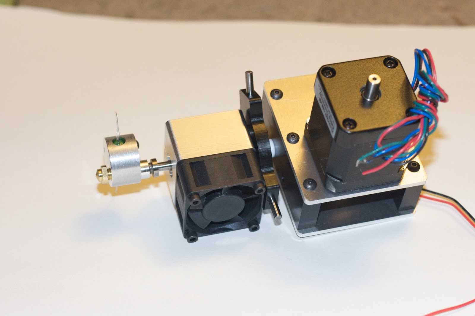
Cutting the fins of a heatsink is generally a tricky one. You want a lot of surface area, and that means deep slots, and thin fins. There are a couple ways to do it, none of them fast. It would be simpler to mount pre-made extrusions to the sides of an aluminum block, but I like machining things so I came up with this design. It is sized to fit a 40mm DC fan directly.


Cutting the fins of a heatsink is generally a tricky one. You want a lot of surface area, and that means deep slots, and thin fins. There are a couple ways to do it, none of them fast. It would be simpler to mount pre-made extrusions to the sides of an aluminum block, but I like machining things so I came up with this design. It is sized to fit a 40mm DC fan directly.

To start the process of cutting the fins, it's best to remove as much material as possible. Deep, narrow slots have issues with chip clearance, and the less material there the better. I drilled these holes, the same pattern from both sides. While I could have packed things a little closer together, I didn't want to risk busting through a wall, and messing things up. Both sides were used because again, at much over 8-10 times the drills diameter deep, things start to get tricky. These did do a good job for their intended purpose.

The depth of the part again poses a problem when trying to mill something like this. The slots are .095" wide, so the most generally available "deep" endmill is .0625". That will cut to ~.4625" deep, almost enough to get halfway through the block. A shallow pocket on the face allowed just enough clearance to get the end mill halfway through. A little more could be removed, but if this doesn't provide enough cooling as is, it's time for a totally new design.

The rear of the block is slotted for clamping action on the stainless thermal barrier tube. You can see the counterbored holes on the side which will facilitate the clamping action. A little breakthrough into the fins was unavoidable with the size of these parts.

The last op was to put this hole pattern into the top. The mount for this extruder will be of a 3 pointed design. The tripod will provide equal contact, positive location, allow the head to move in case of a crash, and even electrically indicate such a crash. It also could serve as a 3D probe, more on this later.
These holes match the pattern in this mount arrangement.
Friday, September 24, 2010
Nozzle Part 2

Work continues on the nozzles, these are almost complete. All that remains to be done is to thread the base to 1/4"-28. I had made 8 blanks, so I drilled 3 to .5mm (0.0197") and 3 to .3mm (0.0118"), leaving 2 "blank". I think I'll try a little smaller at some point, perhaps .25mm or .2mm but I want to get the larger sizes working reliably first. I might also want to attempt to get a smaller filament to make such a small nozzle size easier.

These are the thermal break tubes. 303 stainless steel was used because it machines so well while retaining much of the qualities of stainless steel, such as a relatively poor heat conductivity. The diameter is reduced right after it connects to the heater block. This will hopefully further reduce the amount of heat transferred upwards. The wall thickness here is ~.025". The bore was reamed to size for the smoothest finish I could get. The upper portion will contact the aluminum heatsink. The only thing left to do on these is to cut the wrench flats on the largest diameter section.

These are the blanks for the heatsinks. 1" thick, and 40mm square to match the fan. There are a bunch of operations to do on these before they are ready to use as a heatsink. The altered slightly from pictured earlier. Instead of a separate duct part, I've made the heatsink match the fan size, one less part, and it makes the whole thing smaller. I'm still not 100% that this arrangement will provide enough cooling, but it's worth a shot. With any luck I can get these and the heater blocks done by the end of the weekend. PLA has been ordered, but has not yet arrived, and I have pretty much finalized the extruder drive design.
As is often the case when building things, I get ideas for how I can make it better. Thinking about the construction of the nozzle, it occurs to me that given the right sequence of draw dies, one could easily draw cartridge brass to the right shape, without machining. The wall would be no thicker than the original material, so the reduction would be very small. A flange could also be molded on the end to attach with a flare style nut, perhaps even using an off the shelf fitting. Something to think about for next time.
Wednesday, September 22, 2010
Nozzle Part 1

Today I started on the extruder nozzles. These are made from 360 Brass, which is super easy to machine. I'm saving the threading for later, as I want to grab what will wind up being the threaded section in a collet to turn the tip. I'm aiming for everything around the actual orifice being no thicker than .020". I used a straight flute carbide bit to get the holes very smooth for lower friction, and with a known angle at the bottom (135deg).

More goodies continue to arrive. I decided that the non linearity and tiny size/delicate wires of the thermistor were going to be a problem. Above is the AD595CQ which will go with the bolt-on thermocouple behind it. I still have to come up with a board for this, I am going to try to come up with a single sided shield for the Ardunio to hold this, the FET's for power driving, and stepper output terminals.
Monday, September 20, 2010
Gathering Supplies

Supplies have begun to roll in. Shown here are a single NEMA 17 from Keling and a Gecko 251. I really like these drives, I use them in a slightly different form in the mill. Four of these boards are bundled together along with an opto-isolating breakout board, which makes a lot of things easier and safer. For new people to CNC the G540 is a great way to get into things, without having to do a ton of wiring.
Here the G251 will be driven by one of the Ardunio boards. I got a little crazy at Sparkfun and wound up with a couple with USB, one non-USB variant, and a Lilly Pad for other projects. Also some conductive thread and sew in LED's. Rounding things out are an LCD to display critical info and some button input boards.
I ordered the wire wound resistors, fans, and switching MOSFET's from Digikey. I also picked up some Thermistors, but after some consideration have decided to go with a Thermocouple for temperature sensing. I've read up a bit on the non linearity within the temperature range that I'm trying to measure, and I think it's best to avoid the workarounds to the problem. Although I'm not sure exactly how critical a role constant temperature plays, getting a linear temp reading makes maintaining it easier.
The first of several McMaster orders is a away, and I'm closing in on a design that I'm prepared to machine.
Wednesday, September 15, 2010
It begins
Recently I have become aware of the existence of open source 3D printing technologies, most notably www.reprap.org. A bunch of reading of that site, and other associated blogs, and I am determined to build my own printer. It's not my intent to make a direct copy of the Reprap design, or of several commercial designs out there, but rather to build the best printer I can make for a reasonable budget. Self replication is not one of my prime movers. The RepRap project has helped me an enormous amount, so I do hope that by documenting my build, some folks working on that project might gain some insight or ideas.
I do have a lot of tools, both hardware and software to use to do this. Over the past year and a half or so, I've put together a pretty cool 4 Axis CNC machine.

The major structural components are made from 3"x1.25" 6061 bar stock aluminum. At my last job there was about half a pallet of cut off ends of 20' sticks, maybe 22" long. The fact that this material was free to me was a major factor in the construction of this machine. Most of the work done building this machine was done with a HAAS TM1, which is a small toolroom/prototyping CNC mill. Each axis has two frame rails, which are connected by cross bars. These cross bars are doweled into the rails, and bolted. The sections were then machined flat to accept the recirculating ball linear guides. These are a relatively cheap variety, but almost certainly overkill given the envelope, overall speed of the machine, and spindle horsepower. They do provide a very low friction, as well as slop free motion.

To get things moving ball screws were chosen. Two nuts on each screw with Bellville springs between them take up any backlash between the screw and nuts, and dual angular contact bearings at the driven end eliminates it from that area as well. An old cast iron machine table was "recovered" from a surplus place, and I've reused the head from my old Sherline mill. It's not an ideal solution, one of the current projects involves replacing it with a Sherline "industrial" cartridge spindle, and reworking the head of the mill a bit.

Driving the system are a set of NEMA 23 sized steppers driven by Gecko drives. I really like these drives, as they have a good feature set at a relatively reasonable price. Good service and support as well. Control of the system is a bit of a compromise. Due the the vagaries of legacy hardware support, coupled with newer tech such as power management systems, modern parallel port implementations can frequently be lacking. Hours of testing revealed problems at higher step rates that I needed to get the precision/speed I was looking for. There are relatively niche motion control boards out there, but they are pretty expensive. After testing several options including EMC2, I found the most cost effective way to use the computing hardware I had at hand was to pick up a Smoothstepper USB motion control board. It does force me to use the Windows program Mach3 for control, along with several other minor limitations. Although annoying, living with them is a small price to pay for a machine that cuts parts accurately and without missed steps. A friend had a trunk full of surplus 8020 so I built a stand for the machine.
After the big pieces were squared away I converted the Sherline rotary table to CNC by building a table mount for it and it's stepper. 4 Axis programing is "interesting", either with or without CAM. It has enabled me to make a bunch of cool parts that otherwise would have been impossible.

I'm sure anyone who is familiar with the RepRap and RepStrap is thinking, "Why doesn't he just make a thermoplastic extruder, and slap it on the side?" The short answer is that these mechanics were optimized to move a heavy table and vise, and cut metal and plastics at moderate feeds. At higher feed rates, the increased mass needed to handle the stresses of machining becomes a liability as you have to exert more energy to move it.
The plan is to build a thermoplastic extruder first, testing it with these mechanics. The cartesian bot is relatively trivial to build, especially with the experience of having built the mill. It will be optimized to move lighter loads faster, while maintaining good accuracy.

Extruder design is based heavily on nophead's work. Here is a model of the current design, nothing cut yet, as I still have a few things to button up.

The heater block will be made of 7075 Aluminum, with a split clamping design to grab the resistor. 7075 is chosen over other grades because it machines very nicely, is very strong, and I happen to have an appropriately sized piece of stock handy. Nozzle is threaded male and made of brass. The intent with both the nozzle and the thermal break is to have the flat bottom of the part bottom out on the machined flat bottom of the hole. Threads on the nozzle and thermal break are relived from the end to eliminate tapping to the bottom of the holes. The thermal break will be made of stainless steel. I'm using Alloy 303, as it is considered the most machinable of commonly available grades. It will thread, drill and ream easier which is a great help when dealing with stainless. The thermal break will be turned down for a section to lower the ability to transfer heat upwards, and the heat sink at the top will hopefully cool the top of the thermal break enough. The black portion of the diagram is the mount/duct for a 40mm fan. If this arrangement does not suit, I plan to investigate water cooling. The only PTFE used is to insulate the heater block, and for wire insulation, none under mechanical stress. There is also no adhesive used in this assembly, making rebuilding, adjusting, and modifying easier.
Subscribe to:
Posts (Atom)