I tied up a few loose ends hardware wise, and decided to do some rough testing with the extruder. In order to drive the stepper, I connected it to the 4th axis output of my mill. I turned on the heater circuit, and waited until it hit temp. Then I turned on the stepper power system. This is where the trouble started.
Temperature readings began jumping around wildly, which caused the actual temperature to drop, the system would see that the temp was reading very high and turn the heater off. I was reading the temp through the serial port monitor on the Ardunio. Thinking it might have been a strange ground loop problem, or timing interference on the CNC system with the serial monitor I tried isolating the board. Separate board power supply, and I attached a serial LCD display for temp readout. No difference, still crazy noise when the CNC was on.
I thought noise might be getting through the thermocouple, so I grounded the shield with no change. Although I checked for conduction paths between everything and the thermocouple, I even tried taking the thermocouple off the extruder and moving it and the board across the room.
A little scoping around and I believe I have found the culprit, the switching power supply that drives the CNC. When it's on there is enough noise radiated back into the power line to put 50mv of noise on an oscilloscope with it's probe grounded that is plugged into the same house circuit. An EMI filter is on it's way from Digikey. A new power supply is being researched as well, as I plan on making an all in one power source/cnc controller and I need a supply that will play nice in that app.
The other big thing is that I have decided I am not satisfied with the current extruder design. Although it does function relatively well, I am not happy with it's ease of manufacture. Too many operations on too many parts, and absent a bunch of fixtures, very time consuming to make en masse. Additionally the whole thing seemed rather heavy, and reducing weight in this area would seem crucial to good performance.
I have almost completed a reworking of the heater block, nozzle, tube and heatsink parts. I am still working on a redesign of the filament drive mechanics. This where I feel the most can be gained, this part weighs the most.
Sunday, October 17, 2010
Sunday, October 10, 2010
Electronics 1
Since I am not using the standard electronics to control the stepper motors, I needed to come up with something for temperature control for the extruder head. I could have bought an off the shelf extruder controller and just not used the features on the board that I didn't need. That seemed like a bad solution, and I'd have to add another board anyway to get the thermocouple signal in. I've designed boards before and had them produced by external services, but I didn't want to wait/pay for that this time. I do have a CNC mill at my disposal, and I wanted to try milling a board.

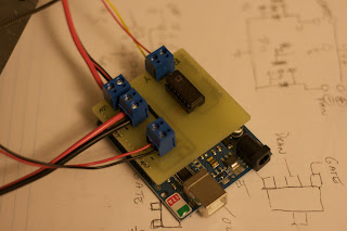


Since the circuit was so simple I designed this in Solidworks rather than a schematic CAD program. The circuit consists of an AD595 to convert the temperature from a type K thermocouple, and a pair of NIF5003 FET's to control power to the heater resistor, and the fan for cooling the heater heat sink. I milled this board using a combination of 1/16" and 1/32" end mills, cutting .003" thick. It's key to make sure that the board is very flat when milling, as errors of a couple of thou will easily be reflected in a cut that shallow. I faced a small metal plate in the vise first, to make sure it was as flat as the mill could make it before double stick taping the board down. I am quite pleased with the result, I'll have to make more boards like this in the future.


Here is the board on top of the Ardunio board I have. You can see the AD595 on top in a socket (no sense committing a $20 chip until you know the circuit works). The two FET's are hidden on the bottom of the board, as they are surface mount, and I only felt like doing a single sided board.
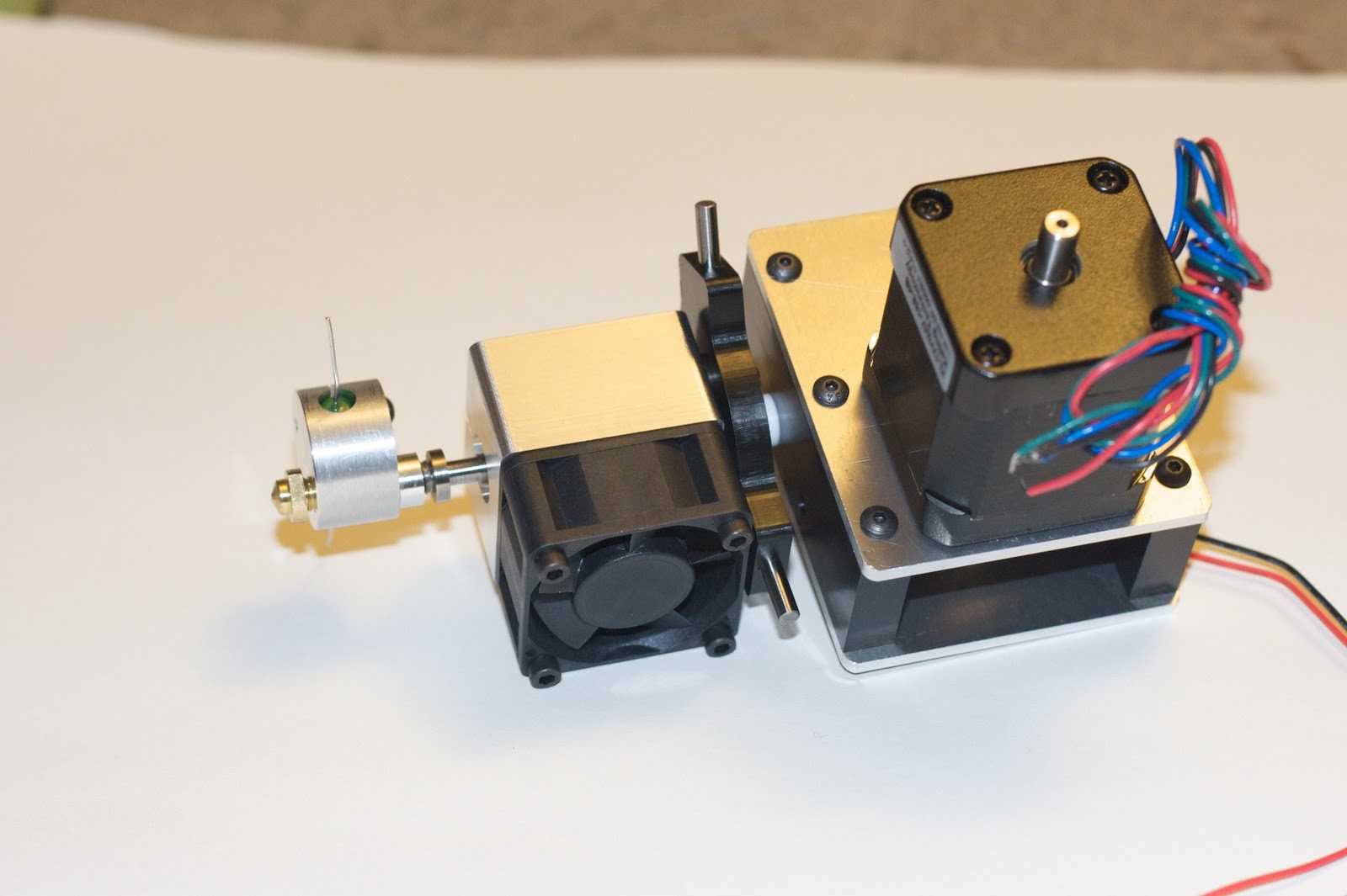
I whipped up some really rough test code to see if I could get some temperature control out of this thing. I'm happy to report that it seems to work well so far. I should really get another thermocouple to confirm temp accuracy. You can also see the PTFE insulator parts around the heater block in the second picture. There are still some minor mechanical things to finish before I can start pumping plastic through it, with any luck I can get that happening later this week.
Saturday, October 9, 2010
The first toolhead nears completion

There was one major part missing from the assembly thus far. There is a need for an easily switchable toolhead so that several designs can be experimented with. I have some rough designs in my head for a much finer extrusion, and hopefully reducing the mass of the extruder significantly. A switchable design will also let me drop in a tangential knife setup, or other options, more on those in a minute. The other big thing that I've not seen is a safety system to protect the head in the event of a crash, and notify the system. Such a system is essential to protect the system during an unattended print if something goes wrong. The lasers at work have a similar system that if the actual head contacts the work, it simply alarms out, and the nozzle is easily pushed back to precise alignment.
Good news is that I think I can kill several birds with one stone. I've basically adopted the same methodology as some simpler 3D probe systems. The above pictured item is kind of the keystone in this setup. Three dowel pins are mounted at 120 degrees to each other. These will set on pairs of bearing balls, providing two points of contact per dowel pin. With 3 pins there will be repeatable location every time. By electrically connecting the balls in series, you can sense if the unit is located or not. By applying spring pressure to the top the extruder will stay still, but if the tip gets knocked away by a warped or attached part the system can safely stop. By mounting a stylus head instead of the extruder you could scan simple objects into point clouds. If nothing else you can determine the exact level of the bed of the machine using this method.

Now I can put together the extruder head. Except for the #8 bolts I'm missing....doh! At least things have gone together enough for this shot. Todays work involves drawing and hopefully cutting the PTFE insulators for the heater block. I'll get the bolts tomorrow. I'd really like to melt some plastic by the end of the weekend, but there's a long way to go.
After much internal debate I have also decided to go with non RepRap electronics. I have a viable CNC drive system already done. The Gecko 4 axis drive that I have uses 9 pin DIN connectors to plug steppers into. Within these connectors there is a current set resistor installed for each motor, so the drive is set per the motor that is plugged in. This will make it easy to make a CNC drive box with the stepper power supply, the 4 axis drive, and the USB step pulse generator. Connections available for limit switches and such available, I'll develop a multi-pin solution so all I need to do is connect 4 steppers and one other plug to switch machines.
Tuesday, October 5, 2010
Filament Drive

Today I worked on the housing for the filament drive system. Pretty simple really, a couple of 1/8" thick aluminum plates, and some delrin to space them apart. As previously mentioned, the drive roller and larger pulley spin on needle roller bearings against a 1/4" diameter shoulder bolt. The front side of the housing has an adjustable shaft that the idler roller rides on. The idler roller is a bronze bushing with rubber bonded to it.

In this side view you can kind of see how all of the pieces fit together. Although I haven't put power to the stepper yet it seems to have plenty of grip on the PLA that I have. It's really hard to see in these pictures, but the delrin is cut for some pieces of 3/8" PTFE rod that I had from another project. I'll drill them out to provide top and bottom guide tubes for the filament. The bottom tube will extend all the way down into the heatsink.
Friday, October 1, 2010
Test Assembly


Progress is a bit slower than I'd like, but I did manage to get enough things done to put together this test assembly of the hot end. I have a 3A 12V power supply kicking around, so I wired it up. I also connected the thermocouple which was removed to take these shots.
The heater reached 210C pretty quickly, I'd say about a minute and a half, possibly less. I didn't leave it connected, as I don't have the circuit boards for the extruder controller put together yet, just connect/disconnect while watching the meter. In this limited test the heatsink stayed relatively cool. More testing is needed to see how it holds up under actual use.
Subscribe to:
Posts (Atom)